kinematic - Kinematic solver/constraint system
This module defines the types and functions for kinematic manimulation and computation.
A Kinematic is a conceptual approach of mechanisms. It sort parts in several groups with the same movement (so in a solid, the solids are all bound together), and it links the defined solids by joints corresponding to the constraints each solid put to the other solids in the joint. That way no matter what are the parts, and what are their shape, even whan surfaces links the solids - the solid always have the same movements when there is the same joints between them.
So to analyze a mechanism we look at its kinematic. And that can be done prior or after the part design as it is independant.
A kinematic in itself is a set of solids, observing movement relations. Those are modeled across the following classes: Solid and Kinematic.
Solids are considered to be rigid, this allows the to use the Screw theory to represent the force and movement variables (see https://en.wikipedia.org/wiki/Screw_theory).
In this module, screws are called Screw.
Tip
In case of rigid solids, torsors makes possible to represent both the translative and rotative part of each movement aspect, independently from the point in the solid.
-
class
Solid(pose=None, **content)[source] Solid for kinematic definition, used as variable by the kinematic solver
A Solid is also a way to group objects and move it anywhere without modifying them, as the objects contained in a solid are considered to be in solid local coordinates. A Solid is just like a dictionary with a pose.
-
orientation rotation from local to world space
Type: quat
-
position displacement from local to world
Type: vec3
-
content objects to display using the solid’s pose
Type: dict/list
-
name optional name to display on the scheme
Type: str
Example
>>> mypart = icosphere(vec3(0), 1)
>>> s = Solid(part=mypart, anything=vec3(0))   # create a solid with whatever inside
>>> s.transform(vec3(1,2,3)) # make a new translated solid, keeping the same content without copy
>>> # put any content in as a dict
>>> s['part']
<Mesh ...>
>>> s['whatever'] = vec3(5,2,1)
-
property
pose: dmat4x4 Transformation from local to global space, therefore containing the translation and rotation from the global origin
-
place(*args, **kwargs) Solid[source] Strictly equivalent to
.transform(placement(...)), seeplacementfor parameters specifications.
-
set(**objs)[source] Convenient method to set many elements in one call. Equivalent to
self.content.update(objs)
-
-
class
Kinematic(joints, fixed=(), solids=None)[source] Holds a kinematic definition, and methods to use it The solid objects used are considered as variables and are modified inplace by methods, and can be modified at any time by outer functions The joints are not modified in any case (and must not be modified while a Kinematic is using it)
-
joints the joints constraints
-
solids all the solids the joint applys on, and eventually more
-
fixed the root solids that is considered to be fixed to the ground
-
property
pose: [mat4] The pose matrices of each solid in the same order as ` self.solids`
-
-
solvekin(joints, fixed=(), precision=0.0001, maxiter=None, damping=1)[source] Solver for kinematic joint constraints.
Unlike
solve, the present solver is dedicated to kinematic usage (and far more efficient and precise). It doesn’t rely on variables as defined by solve, but instead use Solids as constraints.See the joints module for joints definitions.
-
class
Screw(resulting=None, momentum=None, position=None)[source] - A 3D torsor aka Screw aka Wrench aka Twist - is a mathematical object defined as follow:
- a resulting vector R
- a momentum vector field M
- The momentum is a function of space, satisfying the relationship:
- M(A) = M(B) + cross(R, A-B)
- Therefore it is possible to represent a localized torsor such as:
- R = resulting
- M = momentum vector at position P
- P = position at which M takes the current value
- Torsor are useful for generalized solid mechanics to handle multiple variables of the same nature:
- Force torsor:
- Screw(force, torque, pos)
- Velocity (aka kinematic) torsor:
- Screw(rotation, velocity, pos)
- Kinetic (inertia) torsor:
- Screw(linear movement quantity, rotational movement quantity, pos)
All these torsors makes it possible to represent all these values independently from expression location
-
resulting Type: vec3
-
momentum Type: vec3
-
position Type: vec3
Of course, as any vector variables,
Screwimplements+ -with otherTorsor, and* /withfloat
-
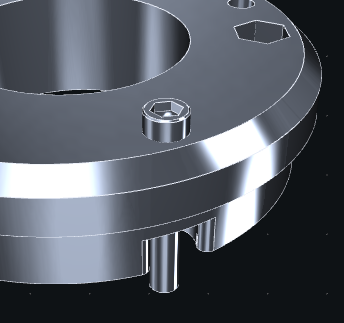
placement(*pairs, precision=0.001)[source] Return a transformation matrix that solved the placement constraints given by the surface pairs
Parameters: - pairs –
a list of pairs to convert to kinematic joints
- items can be couples of surfaces to convert to joints using
guessjoint - tuples (joint_type, a, b) to build joints
joint_type(solida, solidb, a, b)
- items can be couples of surfaces to convert to joints using
- precision – surface guessing and kinematic solving precision (distance)
Each pair define a joint between the two assumed solids (a solid for the left members of the pairs, and a solid for the right members of the pairs). Placement will return the pose of the first relatively to the second, satisfying the constraints.
Example
>>> # get the transformation for the pose
>>> pose = placement(
...             (screw['part'].group(0), other['part'].group(44)),  # two cylinder surfaces: Gliding joint
...             (screw['part'].group(4), other['part'].group(25)),    # two planar surfaces: Planar joint
...             )  # solve everything to get solid's pose
>>> # apply the transformation to the solid
>>> screw.pose = pose
>>> # or
>>> screw.place(
...             (screw['part'].group(0), other['part'].group(44)),
...             (screw['part'].group(4), other['part'].group(25)),
...             )
>>> screw.place(
...             (Pivot, screw['axis'], other['screw_place']),
...             )
suppose we have those parts to assemble and it’s hard to guess the precise pose transform between them
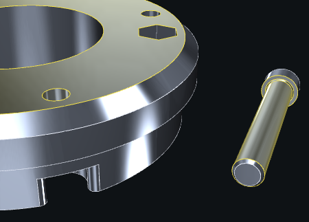
placement gives the pose for the screw to make the selected surfaces coincide
- pairs –
-
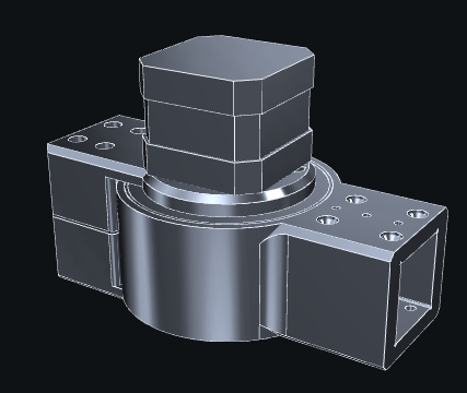
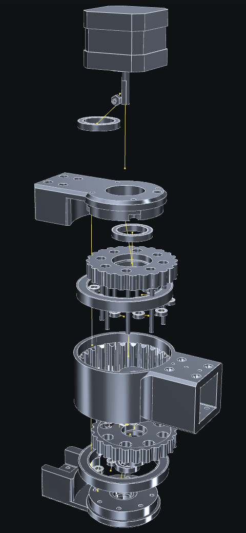
explode(solids, factor=1, offsets=None) -> (solids:list, graph:Mesh)[source] Move the given solids away from each other in the way of an exploded view. It makes easier to seen the details of an assembly . See
explode_offsetsfor the algorithm.Parameters: - solids – a list of solids (copies of each will be made before displacing)
- factor – displacement factor, 0 for no displacement, 1 for normal displacement
- offsets – if given, must be the result of
explode_offsets(solids)
Example
>>> # pick some raw model and separate parts
>>> imported = read(folder+'/some_assembly.stl')
>>> imported.mergeclose()
>>> parts = []
>>> for part in imported.islands():
...     part.strippoints()
...     parts.append(Solid(part=segmentation(part)))
...
>>> # explode the assembly to look into it
>>> exploded = explode(parts)
before operation
after operation
-
explode_offsets(solids) [solid_index, parent_index, offset, barycenter][source] Build a graph of connected objects, ready to create an exploded view or any assembly animation. See
explode()for an example. The exploded view is computed using the meshes contained in the given solids, so make sure there everything you want in their content.Complexity is
O(m * n)where m = total number of points in all meshes, n = number of solidsNote
Despite the hope that this function will be helpful, it’s (for computational cost reasons) not a perfect algorithm for complex assemblies (the example above is at the limit of a simple one). The current algorithm will work fine for any simple enough assembly but may return unexpected results for more complex ones.